Cryo-FIB-Lift-Out for Soft X-ray Tomography
- Abstract number
- 431
- Presentation Form
- Poster
- DOI
- 10.22443/rms.mmc2023.431
- Corresponding Email
- [email protected]
- Session
- Poster Session One
- Authors
- Haneen Packeer Ally (4), Dr Lisa White (1), Dr Kenneth Fahy (3), Dr Christopher Parmenter (2)
- Affiliations
-
1. Biodiscovery Institute, University of Nottingham
2. Nanoscale and Microscale Research Centre, University of Nottingham
3. SiriusXT Ltd
4. University of Nottingham
- Keywords
Cryo-Soft X-ray Tomography, Cryo-FIB-Lift-Out, Cryo-Scanning Electron Microscopy, Cryo-Transmission Electron Microscopy
- Abstract text
Summary -
This research explores the development of a robust sample preparation technique to analyse hydrated biological matter using Cryo-soft X-ray Tomography (Cryo-sXT). We discuss new improvements made to existing techniques, namely the Cryo-FIB-SEM Lift-Out technique which assists in achieving this objective.
Introduction -
Near native state imaging of hydrated biological matter has been the interest of many biologists for years. Techniques such as Cryo-soft X-ray Tomography (Cryo-sXT), Cryo-Scanning Electron Microscopy (Cryo-SEM) and Cryo-Transmission Electron Microscopy (Cryo-TEM) have been utilized to perform near native state imaging. This work seeks to ease the sample preparation process to obtain a site-specific specimen for analysis using the Cryo-soft X-ray Tomography. To accomplish this, we focus on the development of a secure sample preparation technique for the transfer and analysis to the Cryo-sXT utilizing the Cryo-FIB-SEM ‘Slab’ Lift-Out technique. This sample preparation approach consists of three parts which includes the modification of a slot grid, preparation of the specimen slab and the mounting of the slab into the slot.
Methods/Materials -
FIB-SEM was performed on a Crossbeam 550 (Carl Zeiss) or Quanta 3D (FEI company), Cryo-SEM/FIB was done using a Quorum 3010 cryo-stage and preparation stage, with TEM-prep slusher. The lift-outs were done using an Oxford Instruments OP100 with cryo-kit.
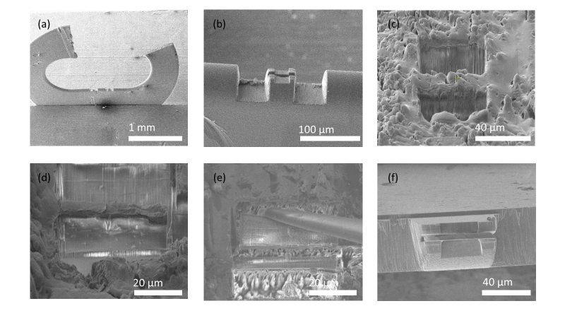
The modification includes the removal of a substantial section off the top of a slot grid (Agar Scientific) leaving a small portion protruding off the side (Figure 1(a)), followed by the FIB milling of slots into the base of the grid. The initial construction of the slots comprises of milling a small portion from the base of the grid at a stage tilt of 0◦, followed by milling in the middle of the pre-milled base at a stage tilt of 52◦ as depicted in Figure 1(b). This creates a slot for the deposition of the slab. The sample used was high-pressure frozen (HPF) in a planchette prior to the experiment and was then Cryo-FIB milled following the pre-existing milling technique1, where the area of interest was preserved and the milling was performed on the front and back of the site (Figure 1(c)), followed by the “J” under cut (Figure 1(d)), to prepare the slab. The attachment of the Omniprobe needle to the slab for the lift-out was secured by either cryo-condensation of water from a gas in injection systems (GIS) or the redeposition of copper (Figure 1(e)). The copper redeposition was carried out using the Omniprobe, where a minute amount of copper was attached to the end of the Omniprobe needle, followed by directing the Omniprobe to the site of attachment and milling the copper for redeposition. The mounting of the slab into the slot was performed at a stage tilt of 0◦ and this was similarly secured with either cryo-condensation or copper redeposition (Figure 1(f)).
Results and Discussion -
The slab lift-out technique amplifies the previous lift-out technique1, in terms of robustness and stability. This is by the security provided at the two ends of the slab to hold itself in place during the exposure to electron beams and X-rays, unlike a lamella attached to one side of a support grid post. Likewise, the copper redeposition used to secure the slab helped avoid the stray water deposition from the Gas Injector System (GIS). The removal of the major portion off the top of the slot grid allows easy access and relative free access during the slab deposition, whilst the protruding portion allows better handling of the grid during the mounting of the grid to the shuttle. The milling of slots onto the slot grids creates a more versatile environment for lift-outs as the dimensions are not limited, as in the case of a pre-fabricated support grid post.
Figure 1: (a) Modification of the slot grid head (b) Modification of the slot grid base (c) FIB milling preserving the area of interest (d) “J” under-cut (e) Slab lift-out (d) Slab deposition into the slot.
Conclusion -
We have demonstrated that the use of the aforementioned techniques and modifications help achieve site specific preparation of hydrated biological matter as a pre-cursor to using the Cryo-soft X-ray tomography.
- References
(1) Parmenter, C. D.; Nizamudeen, Z. A. Cryo-FIB-lift-out: practically impossible to practical reality. J Microsc 2021, 281 (2), 157-174. DOI: 10.1111/jmi.12953 From NLM Medline.