Study of beam damage effect on CPO-27-Ni Metal Organic Framework by Cs-corrected STEM imaging and EELS
- Abstract number
- 95
- Presentation Form
- Submitted Talk
- DOI
- 10.22443/rms.mmc2021.95
- Corresponding Email
- [email protected]
- Session
- Stream 1: EMAG - Soft and Hybrid Materials
- Authors
- Dr. Trung Tran (1), Dr. Dogan Ozkaya (1)
- Affiliations
-
1. Johnson Matthey Technology Centre
- Keywords
MOF, EELS, STEM, low doses, beam sensitive
- Abstract text
Due to a wide range of potential applications [1], Metal Organic Frameworks (MOF) have been extensively studied by various characterisation techniques. Some dedicated scanning transmission electron microscopy (STEM) studies [2-4] have been carried out to image the framework structure, overcoming the notorious beam-sensitivity issue, to gain more detailed knowledge about the material at the atomic level. The central approach for STEM imaging is to get the right electron beam dose for the specific imaging technique used. For instance, it is important to know at which dose the framework geometry starts collapsing and which dose some specific chemical bonding is about to be broken. Here we present a study of CPO-27-Ni MOF (Sigma-Aldrich) to establish the level of beam dose appropriate for high resolution STEM imaging and. We also used STEM electron energy loss spectroscopy (EELS) to probe the structure collapse. This work was carried out using the probe-corrected JEOL ARM200CF operating at 200 kV, post-columned by a Quantum GIF EELS spectrometer equipped with a scintillator-based camera as the detector.
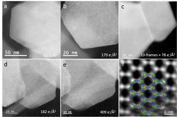
Figure 1. STEM-imaging of CPO-27-Ni framework at different beam doses: a) 63 e-/Å2; b) 179 e-/Å2; c) sum of 10 imaging frames with 78 e-/Å2 for each frame; d) 182 e-/Å2; e) subsequent dose of 409 e-/Å2 on a sub-area of d; f) Fourier-filtered extract from d, superposed with CPO-27-Ni model (Ni atoms in green, O atoms in red, C atoms in blue, H atoms are not shown).
Figure 1 shows different CPO-27-Ni crystals with resolved framework structure imaged using different doses applied by a probe-current of ~ 2 pA. It is observed that the doses can be increased from around 60 e-/Å2 to around 400 e-/Å2 (Fig. 1a, b, d, e) for better pixel sampling while the framework structure still stands. When the doses are built up subsequently to a higher value (~780 e-/Å2) by a series of fast scan frames, the framework is still intact, and the frame-summed image has better signal-to-noise (Fig. 1c). This multiple-frame imaging was acquired with the software tool SmartAlign [5]. Figure 1d&e also show that an additional dose of 409 e-/Å2 subsequently applied on top of a previous 182 e-/Å2 scan did not harm the framework appearance. However, when a dose of above ~ 500 e-/Å2 was applied in a single scan that took around 10 seconds, the collapse of the framework was observed. These observations imply that the accumulation rate of beam impact can be an important factor for triggering damage. As shown in Figure 1f, the framework geometry can be imaged without any apparent damage. However, the pixel sampling (restricted the by the allowed doses) is still too low to resolve the individual Ni atomic columns apparent from the structure model superposed on the image.
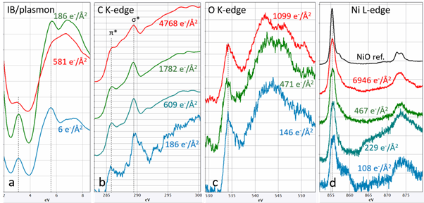
Figure 2. STEM-EELS acquired with different beam doses: a) IB/plasmon; b) C K-edge; c) O K-edge; d) Ni L-edge.
Compared with imaging the framework for appearance of damage which can be caused directly by knock-on or indirectly by radiolysis processes, EELS may be more sensitive in observation of beam impact effect as EELS directly records the instant consequences of inelastic electron scattering. Figure 2 shows STEM-EELS spectra for Interband (IB)/plasmon, C K-edge, O K-edge, and Ni L-edge with energy resolutions of an ZLP-FWHM of 0.55±0.05 eV was for IB/plasmon, C K-edge, O K-edge, and 0.475±0.025 eV for Ni L-edge. In the IB/plasmon region, a prominent peak at ~ 3.1 eV can be observed (Fig. 2a) by a very low dose of ~6 e-/Å2 . Although the peak may be associated to an IB transition, the nature of it is difficult to understand. For CPO-27-Ni (C8H6Ni2O8), π plasmon of C is also expected in this region which could be pointed to the second peak (Fig. 2a, 6 e-/Å2) at ~5.6 eV. These featured peaks were still prominent when a dose of ~186 e-/Å2 was used but flatten down by a dose of ~581 e-/Å2, confirming the significant beam damage for doses above ~500 e-/Å2. The difference in C K-edge spectra acquired at ~186 e-/Å2 and ~609 e-/Å2 also suggests consistently the damage triggering doses. The π* and σ* peaks of C K-edge still show up for a dose of ~1782 e-/Å2 suggesting some durability of the benzene ring. However, the sp2 bonding was weakened by a dose of ~ 4768 e-/Å2 seen as the flattening of the π* peak. In the case of O K-edge (Fig.2c), there was no noticeable change in the spectra when the doses were increased from ~146 e-/Å2 to ~1099 e-/Å2 . It is possible that some subtle features could not be picked up at the current level of signal/noise or some beam impact affecting Ni-O-C linkage had already occurred at ~146 e-/Å2 . As observed in Figure 2d, disturbance to the d band of Ni can be seen for a dose of ~ 229 e-/Å2 compared with the ~108 e-/Å2 . For a dose of ~ 467 e-/Å2 , the Ni L2,3 spectrum starts to resemble the state of NiO, suggesting that the O-C linkage might have been damaged. The spectrum did not change significantly for a dose of ~ 6946 e-/Å2.
In conclusion, by experimenting with different beam doses for STEM-imaging and EELS, a picture of beam damage effects on CPO-27-Ni MOF can be sketched. Generally, the framework geometry can be imaged with a single-scan dose less than ~500 e-/Å2. Some higher total doses may be gradually applied by multiple-frame scheme for better signal-to-noise. EELS experiments suggested that the beam damage process starts from the O-C linkage.
- References
[1] Kuppler, R. J. et al., Coord. Chem. Rev., 2009, 253, 3042.
[2] Mayoral, A., et al., ChemCatChem, 2015, 7, 3719.
[3] Li, Y., et al., Matter, 2019, 1, 428.
[4] Liu, L., et al., Comm. Chem., 2020, 3(99), 1.
[5] Jones, L., et al., Adv. Struct. Chem. Ima., 2018, 1:8, 1.