Improved magnetic field mapping of Fe60Al40 embedded nanomagnets by precession-corrected STEM-DPC
- Abstract number
- 89
- Presentation Form
- Submitted Talk
- Corresponding Email
- [email protected]
- Session
- Stream 1: EMAG - 4D-STEM
- Authors
- Mr Gregory Nordahl (1), Dr Damien McGrouther (2), Dr Magnus Nord (1)
- Affiliations
-
1. Department of Physics, Norwegian University of Science and Technology
2. School of Physics and Astronomy, University of Glasgow
- Keywords
4D-STEM
STEM-DPC
Precession
- Abstract text
In scanning transmission electron microscopy (STEM), a useful technique for quantitative analysis of ferromagnetic domains is differential phase contrast (DPC). A necessity for this technique is a detector geometry that can record electron beam phase shifts in the diffraction plane, described by the Aharonov-Bohm effect [1]. Segmented detectors have previously been the go-to choice, however, the advent of fast pixelated direct detection technology has made 4D-STEM possible [2], with one of the outcomes being improved imaging of magnetic fields by the STEM-DPC technique [3]. With this detector technology, structural information can be extracted simultaneously in conjunction with magnetic information, given that the selected camera length is low enough [4].
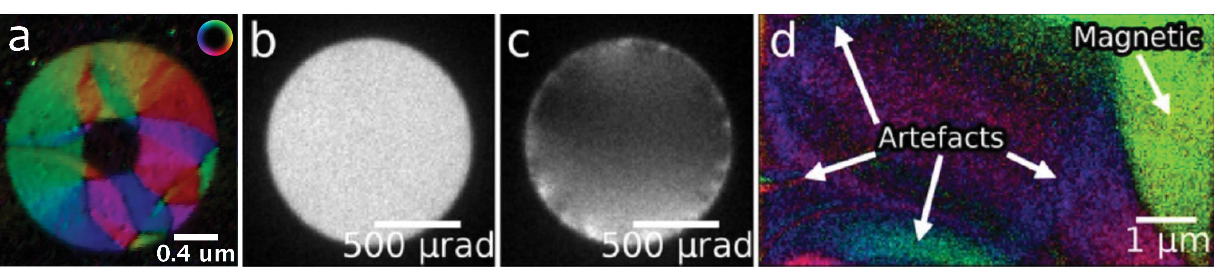
Since magnetic information is typically extracted from the bright field disk containing the unscattered electrons, anything that can disrupt the uniformity of the central disk may lead to unreasonable estimation of the field strength or direction, or even present magnetic contrast where there should be none. Contrast mechanisms other than magnetic, such as diffraction contrast due to local crystal orientation or dynamical diffraction effects, are often unavoidable causes of beam inhomogeneity [3]. An example illustrating artefacts in STEM-DPC imaging resulting from Bragg diffraction can be seen in Figure 1. A good representation of an undisturbed bright field disk can be seen in (b), while (c) shows the effect of inhomogeneities due strong Bragg diffraction on the bright field disk, which result in artefacts as seen in (d).
In this presentation, we will present our work utilizing beam precession as means to alleviate diffraction contrast artefacts in STEM-DPC data. The quality of structural information contained in diffraction spots is also improved by precession, due to a larger degree of diffraction space sampling and reduction in dynamical diffraction effects [5]. Similar studies have been performed where precession-corrected STEM-DPC have been used to study electric fields [6]. Studying magnetic fields with STEM-DPC, however, requires the objective lens to be turned off as to not saturate the magnetic structure immersed in the lens field. The technique is applied on Fe60Al40 ferromagnetic nanostructures embedded in a non-ferromagnetic film. The film matrix, an ordered, paramagnetic B2 structure, is irradiated by Ne+ ions to create desired shapes of disordered, ferromagnetic A2 structure, with a slightly increased unit cell parameter [4]. Figure 1(a) shows a STEM-DPC image of a ring-shaped ferromagnetic structure, created by Ne+ ion irradiation of a Fe60Al40 film. The work was performed on a non-corrected JEM-2100F, equipped with a MerlinEM fast pixelated detector and a NanoMEGAS DigiSTAR instrument for precession control.
Figure 1. (a) STEM-DPC image of an embedded, ring-shaped ferromagnetic structure in Fe60Al40. Different colored regions correspond to ferromagnetic domains, with color wheel showing direction and magnitude of magnetization. Image of bright field disk from a region (b) without strong Bragg diffraction and (c) with strong Bragg diffraction. (d) STEM-DPC image of single-crystalline magnetic thin film. Bragg diffraction effects caused from structural variations are interpreted as magnetic beam shifts, leading to artefacts resembling magnetic fields.
- References
[1] J. N. Chapman, I. R. McFadyen, S. McVitie, IEEE Trans. Magn. 26, 1506 (1990).
[2] C. Ophus, Microsc. Microanal. 25, 563 (2019).
[3] M. Krajnak, D. McGrouther, D. Maneuski, V. O’Shea, S. McVitie, Ultramicroscopy. 165, 42 (2016).
[4] M. Nord, A. Semisalova, A. Kákay, G. Hlawacek, I. MacLaren, V. Liersch, O. M. Volkov, D. Makarov, G. W. Paterson, K. Potzger, J. Lindner, J. Fassbender, D. McGrouther, R. Bali, Small. 15, 1904738 (2019).
[5] P. A. Midgley, A. S. Eggeman, IUCrJ. 2, 126 (2015).
[6] L. Bruas, V. Boureau, A. P. Conian, S. Martinie, J. L. Rouviere, D. Cooper, J. Appl. Phys. 127, 205703 (2020).